


SELF-SANITIZATION AGAINST BACTERIA AND FUNGI
Close
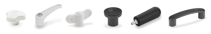
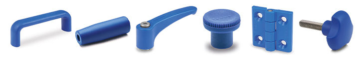
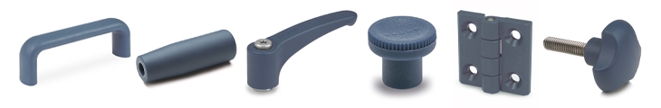
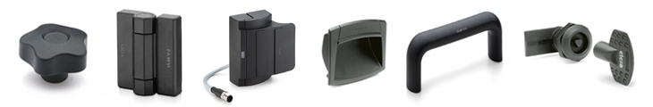
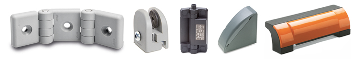
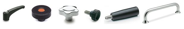
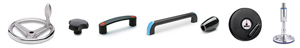
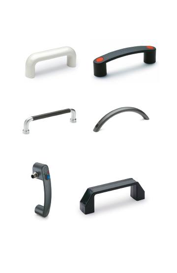
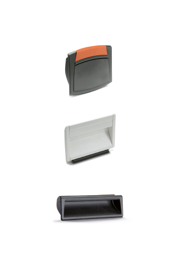
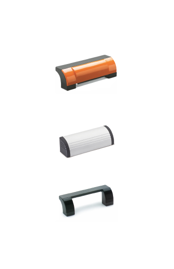
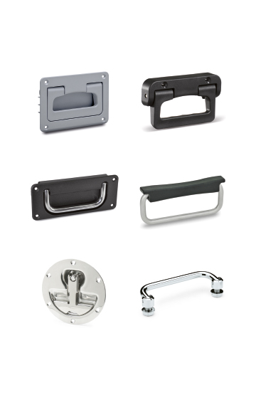
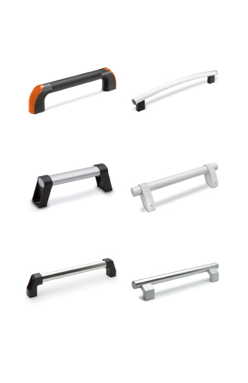
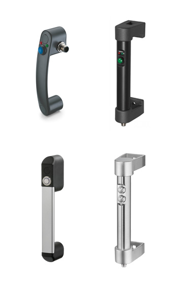
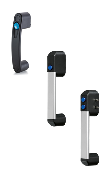
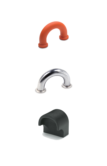
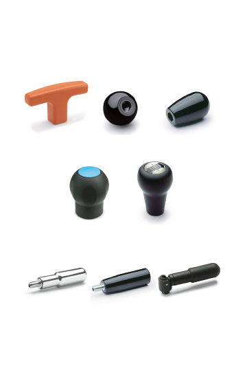
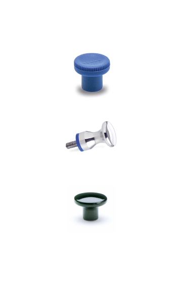
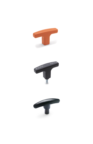
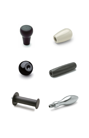
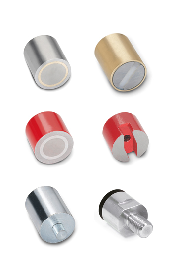
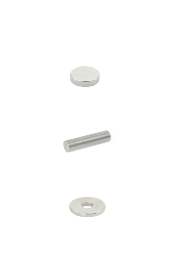
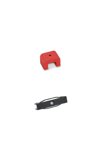
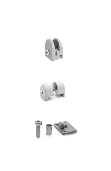
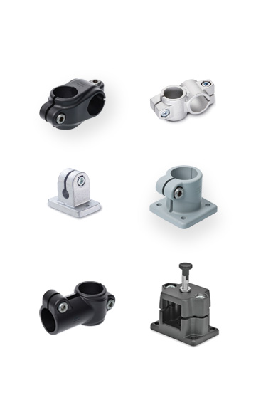
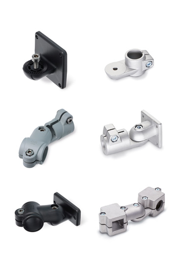
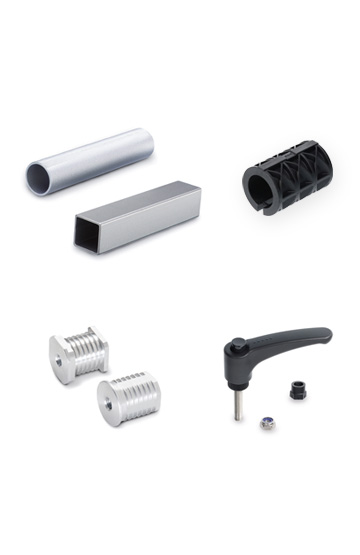
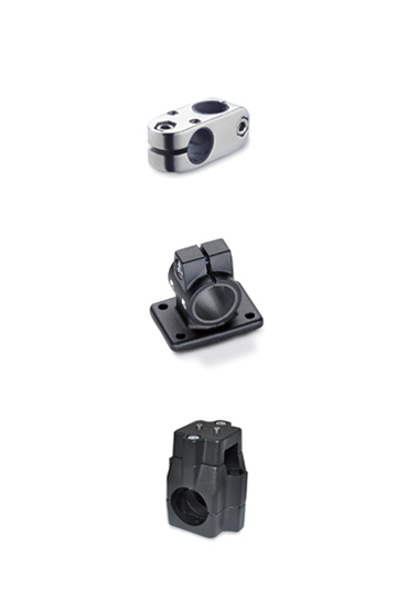
Corrosion resistant, ergonomic, compact shapes in choice materials with easy-clean finishes
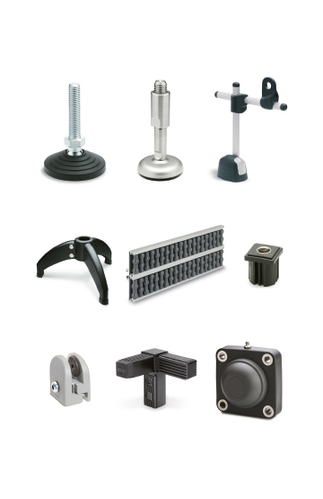
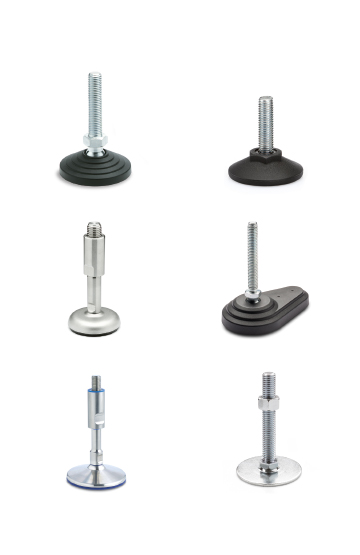
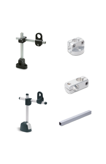
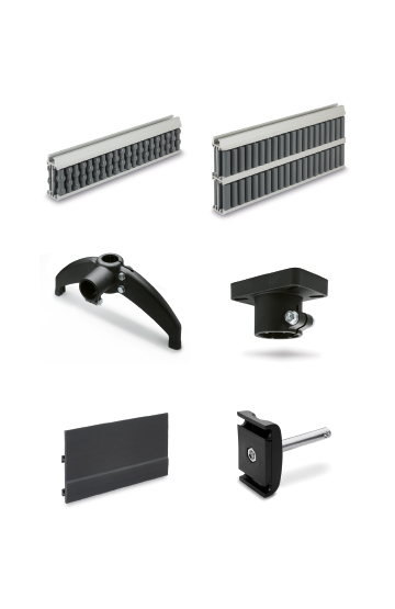
Components for construction vehicles, equipment and machinery
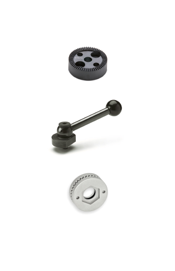
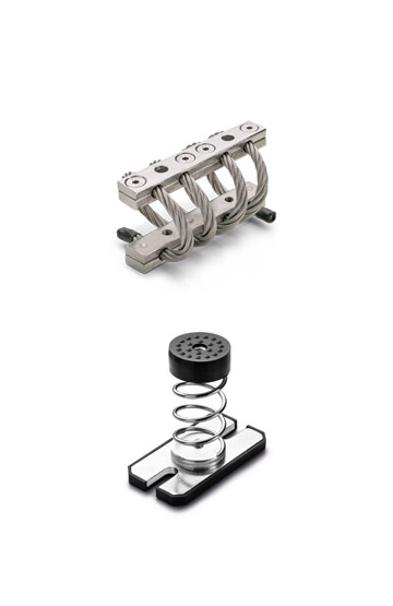
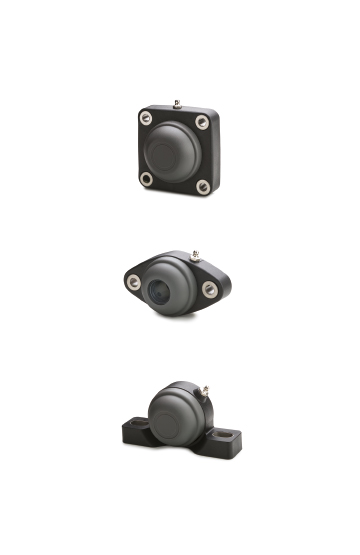
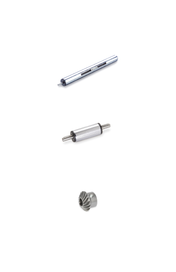
Housing
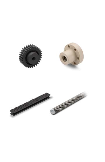
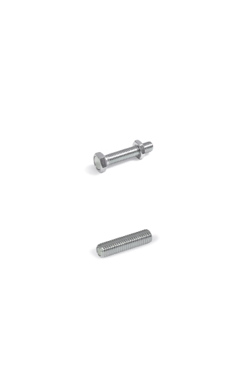
Worm screw, steel
Worm wheel, brass
Ball bearing
Working temperature: from -20°C to +60°C.
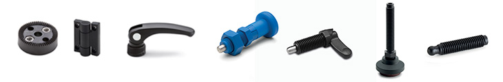
Worm gear reducers GN 3975 can transmit high torque despite their very compact dimensions. They can readily be used for a multitude of applications, such as incline adjustments or to change the direction of shaft rotation.
They can readily be used for a multitude of applications, such as height adjustments or to change the direction of shaft rotation. The parallel keys can take any angular positions.
Depending on the gear ratio, there may be no static self-braking between the worm screw and worm wheel, meaning that the worm wheel can be turned out of a resting state by a torque coming from the output end.


| Circumferential backlash at the drive shaft | 1° ± 0.5° |
| Shaft direction of rotation | Any |
| Worm wheel set design | Left-hand |
| Life expectancy (guideline) | 1.000 hours under full load at a rotational speed of 500 rpm, |
| assuming the gear box is operating for 20% of every 5 minutes | |
| (1 minute of operation + 4 minutes break) at an ambient temperature of 20 °C | |
| Maintenance | Permanent lubrication with grease, maintenance-free |
| m1 | Gear ratio | Max. input torque in Nm* | Max. output torque in Nm* | Input side | Output side | Efficiency in % | Selfbraking | ||||||
| at 100 min-1 | at 500 min-1 | at 1000 min-1 | at 100 min-1 | at 500 min-1 | at 1000 min-1 | Max. radial force in N** | Max. axial force in N*** | Max. radial force in N** | Max. axial force in N*** | ||||
| 20 | 5 | 2.9 | 2.3 | 1.7 | 10 | 8 | 6 | 200 | 200 | 500 | 500 | 70 | - |
| 20 | 13 | 2.1 | 1.8 | 1.5 | 15 | 13 | 11 | 200 | 200 | 500 | 500 | 56 | - |
| 20 | 15 | 1.5 | 1.3 | 1 | 12 | 10 | 8 | 250 | 250 | 500 | 500 | 52 | - |
| 20 | 18 | 1.1 | 0.9 | 0.7 | 11 | 9 | 7 | 250 | 250 | 500 | 500 | 55 | - |
| 20 | 23 | 0.9 | 0.7 | 0.5 | 10 | 8 | 6 | 250 | 250 | 500 | 500 | 50 | - |
| 20 | 30 | 0.6 | 0.5 | 0.4 | 8.5 | 7 | 5.5 | 350 | 350 | 500 | 500 | 45 | - |
| 20 | 40 | 0.35 | 0.31 | 0.31 | 5.5 | 4.8 | 4 | 400 | 400 | 500 | 500 | 39 | x |
| 20 | 65 | 0.24 | 0.2 | 0.2 | 4.5 | 3.8 | 3 | 500 | 500 | 500 | 500 | 29 | x |
| 30 | 5 | 5.4 | 4.9 | 4.3 | 19 | 17 | 15 | 400 | 300 | 800 | 800 | 70 | - |
| 30 | 10 | 3.4 | 3.1 | 2.8 | 20 | 18 | 16 | 400 | 300 | 800 | 800 | 58 | - |
| 30 | 17 | 2.2 | 1.9 | 1.8 | 17 | 15 | 14 | 400 | 400 | 800 | 800 | 46 | - |
| 30 | 20 | 1.7 | 1.6 | 1.4 | 15 | 13.5 | 12 | 800 | 400 | 800 | 800 | 43 | - |
| 30 | 25 | 1.3 | 1.2 | 1.1 | 13.5 | 12 | 11 | 800 | 800 | 800 | 800 | 41 | - |
| 30 | 34 | 1.2 | 1.1 | 1 | 12 | 11 | 10 | 600 | 800 | 800 | 800 | 29 | - |
| 30 | 45 | 0.9 | 0.8 | 0.8 | 10.5 | 9.5 | 9 | 700 | 600 | 800 | 800 | 25 | - |
| 30 | 64 | 0.5 | 0.4 | 0.3 | 8.5 | 7.5 | 6 | 700 | 600 | 800 | 800 | 27 | x |
* Input side speed
** At axial force = 0
*** At radial force = 0
Do not exert any forces onto the housing or into the bearings during assembly. Use of the threaded holes d8 in the shaft is recommended.
The use of a corresponding coupling is recommended to compensate for manufacturing-related shaft offsets and runout tolerances as well as for damping vibrations and shocks.